
Restoration of Macro Texture (Retexturing)
| As a result of natural
in - service wear, or binder migration, road surfaces can become very smooth and exhibit very low friction values which, particularly in wet conditions, can give rise to dangerously slippery surfaces that may cause vehicles to skid or aquaplane (hydroplane) exposing national and local Government authorities to potential liability for claims. The historical method of overcoming this problem has been to apply a new wearingcourse or to surface dress. Studies regarding surface texture and Retexturing methods began in the mid-1980’s in the UK but until the mid-‘90’s, these were limited to mechanical processes. In 1995, the TRL produced Reports 298 & 299 following process trials. DMRB-Volume 7 contains standards and tables concerning skid resistance levels and Chapter 11 covers Retexturing techniques. Chapter 11 also sets out objectives and main ‘stated’ advantages of Retexturing as a Primus Operandi of highway maintenance. These are as follows: • Conserves natural resources • Preserves infrastructure • More economical than traditional surfacing methods • Most processes are weather independent • Disruption to traffic is reduced • Useful ‘stop-gap’ measure to treat small – high-risk sites TRL reports 322 & 367 indicate the importance of texture depth even on low speed carriageways, being important for drainage and low acoustic values and for ensuring that the micro texture provided by the aggregate is sufficiently exposed to optimize skid resistance values. With the development of hydrotechnology it is now possible to re-texture pavement surfaces quickly and efficiently and affordable. |
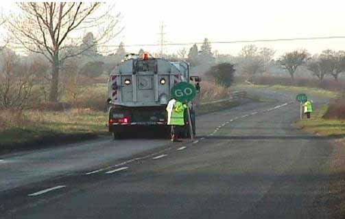
| In the above example,
the working width of the unit is 2300mm (maximum working width is 2800mm and minimum 500mm.) Water at a pressure of between 200 and 550 bar was applied via a hydraulically driven rotating arms containing variable angle nozzles, which are completely contained within their own housing to prevent egress of water and for safety. Traffic management is established at the limits of the working site and whilst operational, traffic is controlled by mobile ‘stop’ and ‘go’ operatives, who are linked by two-way radio sets. Because rates of progress are routinely achieved of 8-10 linear meter’s/minute, delays to traffic are minimal. |

| Located immediately
behind the cleaning unit is the high power vacuum extraction system, which removes the water and arisings at the point of treatment, leaving the surface clean and virtually dry, in a single-pass operation. The required degree of ‘roughness’ is achieved by the use of different nozzles that are matched to the surface being treated and the required result. |